


- Textile Accessories
- Shuttle Loom Parts
- Textile Equipment
- 1511 Textile Machine Parts
- 1515 Textile Machine Parts
- GA615 Shuttle Loom Parts
- Textile Hardware And Tools
- Weaving Machinery
- Textile Auxiliary Equipment
- Textile Picker and Buffer
- Textile Wooden Parts
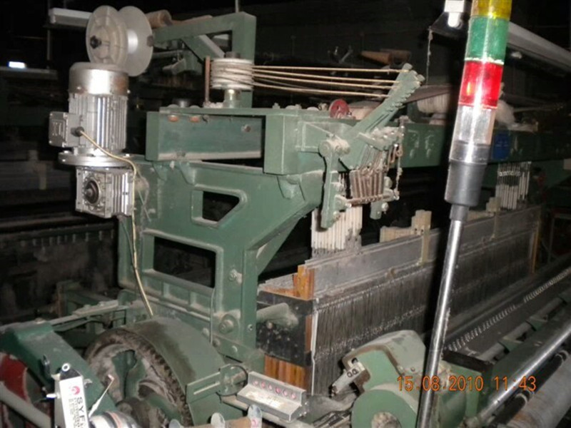
Installation And Debugging Of GA747 Rapier Loom
The 1 car before, must be multi arm mechanism (0111, 0112) and broach hook (0151B) release, otherwise the heald arm (0143) and the blade (0161) with contiguous heald arm provided at the adjusting block (0144) is easy to damage.
2 lever release comprehensive homemade box and return the box hook, with a rope tied heald frame.
3. disengage the connection between the nylon wire rope and the lift arm.
4. remove the multi arm shedding mechanism, front housing assembly (0100-6), and remove the tubing.
5. remove the set of textured paper (0399) and plain paper drive shaft assembly (0300-5).
6. remove the chain tensioner wheel, find the chain connection card and remove the chain.
Remove the pan with a 7 (0400-9).
8. remove the gear cover plate (0228).
9. remove the signal gear housing (0213) and the signal shaft signal gear (0212), and remove a set of bevel gear shaft assembly.
10. loosen the screws for the left and right small wall panels, remove the left small wall panel (0124A) and the right small wall panel (0125).
11. remove the main bevel gear (0207A) outside the main cam.
12. remove the reset chain and the reset spring.
13. remove the broach, swing arm, top broach (0111) and drop knife (0112). The circlip is best to be removed only at the outside, and when the handle is lowered, the circlip shall be replaced.
14. loosen the main cam support (0127A) screw and take off the main cam (0126A)
15. disengage the connection between the lifting arm (0143) and the blade (0161).
16 loosen the heald arm fixing shaft (0141) of the support screw, a heald arm fixing shaft, turn off all the heald arm (0143).
17. loosen the blade support shaft (0132), support the head screw, rotate the blade support shaft, make the blade support shaft plane downward, and then take the blade (0159) in turn.
18. take down the upper and lower hook assembly (0100-9A) in turn.
19. successively take the long vertical needle (0108) and the short vertical needle (0109)
20. loosen the connecting screws of the horizontal needle swing arm (0326, 0327) and the connecting board (0324, 0325).
21. remove indexing cam (0306), adjusting frame, swing lever assembly (0300-9), horizontal pin, swing bar (0328, 0329) and so on
22. loosen the connection between the pushing needle board and the horizontal needle pushing tool connecting rod (0356), and take off the pushing needle board (0359).
23. take the short horizontal needle (0364) and the long horizontal needle (0365) in sequence, and note that the probe can not be pulled out of the probe plate (0367) and the lower probe plate (0368).
24. loosen the horizontal needle connector (0373).
1 loading arm (0143) heald heald arm fixed shaft from the machine after the penetration (0141), turn on after the heald arm clamping piece (0142), heald arm, heddle clip arm premise (0142), adjust the heald arm clip, the heald arm and the hook on tight alignment fastening screw.
2. mount 20 retractor assemblies (0100-9) in turn, and check whether the retractor joint is flexible.
The 3. blade (0159) rotates the blade support shaft (0132), and the blade (0159) is arranged in turn. When the blade is finished, the front end of the blade shall be hooked with the retractor joint and rotate the blade support shaft so that the blade supporting shaft plane faces outwards, and the front face of the spindle head shall be flush with the outer side of the small wallboard to tighten the fastening screw. Check blade movement for flexibility.
The 4. is provided with a blade assembly (0161) to connect the blade back end to the lifting arm, and the front end is connected with the blade and is provided with a nylon wire rope binding piece.
5 adjust the wire rope guide wheel and the installation position of the heald box, the first piece of heald arm, wire rope guide pulley, the heald arm is in the same vertical line. Adjust the length of the wire rope and adjust the nuts of the heald hook so that all the heald frames are flush.
Before the installation and installation of the 6. horizontal needle, do not tighten the horizontal pin connecting body (0373) screw, note that the inner cross pin is left to the outside of the outer platen. A long horizontal needle (0365) is installed in the lower layer, and then a short transverse pin (0364) is mounted on the upper layer. (1) the long transverse needle upward, the long probe also upward, through the short probe (0371) in the hole, and then into the transverse needle plate (0313) in the hole, and finally into the transverse needle plate (0377) of the bottom hole (2) will bring short transverse needle upward, insert transverse needle plate (0376) in the hole, and then through the long hole probe (0370), and finally into the transverse needle plate (0377) of the upper hole. Note: there is a pressure spring (0366) transverse needle, needle plate transverse hole is provided with a corresponding groove, insert must be rotated 90 degrees, to prevent from cross transverse needle needle plate; transverse needle without pressure spring, no groove hole corresponding to the transverse needle plate.
7. insert the long vertical needle (0108) and the short vertical pin (0109) (1) to insert the short vertical needle (0109) first, for the sake of beauty, the short vertical pin head (0110) faces outwards. (2) insert a long vertical needle (0108). For the sake of beauty, the long vertical pin shall be inserted into the inner side of the next long vertical pin. Note: each vertical needle through a two transverse needle, the needle should be set in a long vertical short transverse compression spring and no pinhole of the pressure spring long horizontal hole, short vertical needle on the contrary.
The 8. pushing needle plate (0359) is arranged in the case that the paper has holes, and the probe enters the paper hole, and the horizontal needle falls on the pushing needle board (0359), and the pushing needle board is in the outermost position at this time. In this condition, the clearance between the end of the transverse needle and the inner end of the needle plate should be adjusted from 2 to 2.5mm. This adjustment is adjusted by loosening the retaining screws of the horizontal needle pushing link (0356). Note: fixed on the needle pushing plate (0359) screws between each other not collide, and push the needle plate (0359) screws can not touch the transverse needle plate body (0373); the adjacent transverse needle plate connecting body can not collide; transverse needle knife pushing rod (0356) gasket not default, screws otherwise, easy to cause the transverse needle knife pushing rod damage.
9. install the main cam (0126A) (1) with the long mandrel inserted into the assembly hole of the left wall panel (0101) and the right wallboard (0102). The main cam is mounted on the main camshaft and close to the left and right wall panels, and the locating holes shall be sheathed on the long mandrel. (2) before the machine, mount the main cam bearing (0127A) on the main projection shaft and screw in the screw hole of the cam through the four through holes of the main cam support with four fastening bolts (it can not be fastened at this time). Tighten the clamping screws for the main cam support and tighten the four screws. After the main cam bearing clamping screw is tightened, the four fastening screws are removed, the main bevel gear (0207A) is sheathed, then the four fastening screw is screwed into the screw hole of the cam, and the four screw is tightened. Note: when the main cam is positioned, 1 and 3 are the same direction, 2 and 4 are identical. The main cam can not be slit with the left wall panel (0101) and the right wall panel (0102), otherwise, the main camshaft will be affected by the installation of the left and right small wall panels.
10 mounted on the arm of a broach, the circlip must be put back, and then loaded on the chain reset and reset spring, check the broach swing arm and the main cam contact degree, if there is a gap, the swing arm must replace the broach. Note: the broach guide shaft (0119) and the guide wheel (0139) do not fall off; the swing arm of the broach can not be reversed, and the oil port must face upwards.
11., mounted on the left and right small wall panels, mounted on a cone gear shaft assembly, pay attention to the main bevel gear (0207) and the connecting gear (0208), the top flush.
12. sets of upper indexing cam (0306), adjusting frame, swing lever assembly (0300-9), horizontal pin clamp, swing rod (0328, 0329), and two tension springs (0337, 0338), etc..
13. mount embossed paper and corrugated paper, drive shaft assembly (0300-5) a set.
14. fit the tubing. Note that the tubing can not rub against the oscillating arm and other high speed parts, otherwise it will damage the tubing.
15. fit a chain and tensioning wheel. The tension wheel is adjusted so that the tension of the drive chain is right, and the driving sprocket and the tension wheel are in the same straight line position.
16 mounted on the oil pan with a (0400-9).
1: adjust the location of the probe and the paper hole:
(1) loosen the fastening screws on the drawing paper drive shaft assembly, pull the disc (0320), and gently rotate the paper, drive shaft assembly, adjust the front and back positions of the pattern paper hole and the probe, so that the probe is located in the center of the pit hole before and after. At this point, it should be confirmed that the adjusting roller should be in the concave part of the disc, and then tighten the fastening screws.
(2) loosen the fastening screw on the tight ring of the paper driving shaft assembly, adjust the hole on the paper and the probe in the left and right sides, and make the probe around the center of the hole. At this time, the inner wall of the small wallboard and the clearance of the tight ring should be in the range of 0.1 ~ 0.2mm.
(3) check whether the paper pad wheel (0316) blocks the hole, and if it blocks, remove the pattern paper and fix the paper wheel again.
Two, the probe and the profile of paper clearance adjustment: needle swing rod is installed on the transverse plate (0328, 0329) on the roller (0338) in the spring under the action of compression in the cam (0306), rotary indexing cam, the roller working movement in the largest, the probe from paper, space probe from the paper is connected by adjusting the transverse needle plate (0373) to achieve. Clearance range should be about 1.5 ~ 3mm, and require the right and left at the same time, tighten the horizontal needle, pressure plate connector and horizontal needle pressure bar, swing rod fastening screws. If the gap is too small, and the paper probes will lead to friction, paper damage or probe bending; if the gap is too large, may push the needle plate transverse needle and a needle pushing plate collide, affect normal movement. Note: if not at the maximum radius of cam adjustment, equipment running, cross needle and needle pushing plate together, to push the needle plate cannot move, thus affecting the liftingheald smoothly.
Three, pull the pin and the clearance adjustment dial addendum: rotary indexing cam (0306), the adjusting frame (0333) cam roller (0331) position, the pull pin cam (0307) will enter in the dial (0320) and addendum addendum to separate from the two position. Pull the pin and pull the top of the tooth gap size is consistent, if the gap is uniform, moving the cam roller (0331) in the regulation of the shelves inside and outside the machine position into the gap, the cam roller (0331) to move in the machine; otherwise, it moves to the outside of the machine. Note: after adjusting the adjusting frame, the center of the paper holes and the probe shall be readjusted. At this time, do not move the adjusting frame cam roller.
Four. Install signal gear (0212):
(1) the sprocket wheel of the multi arm opening mechanism is turned forward so that the upper broach (0111) is returned to the final position.
(2) turn the signal shaft, so that the upper retractor is pushed up to reach the highest position, reversing the signal axis, so that the retractor slightly down.
(3) set the signal gear and tighten the screw. Note: when the signal gear is mounted, the signal shaft moves about 0.2mm.
Five. Adjust indexing cam:
(1) forward rotation of the multi arm opening mechanism sprocket, so that the outer side of the upper and lower side of the cutter is perpendicular to each other.
(2) adjust the indexing cam, so that the indexing cam axis, pull pin, pull the axis line three collinear, tighten the indexing cam screws. Six, the opening time adjustment: turn the handwheel by hand loom, the multi arm device on the outer side of the knife, the drop in the same vertical line, the multi arm device in IMIS position. Fixed screw loose dobby device on the drive sprocket rotation, loom handwheel, the loom in the heald level position, and then tighten the fastening screws multi arm device of the sprocket, the multi arm device and loom in the heald level position at the same time. To achieve the time synchronization of loom and dobby device opening time.